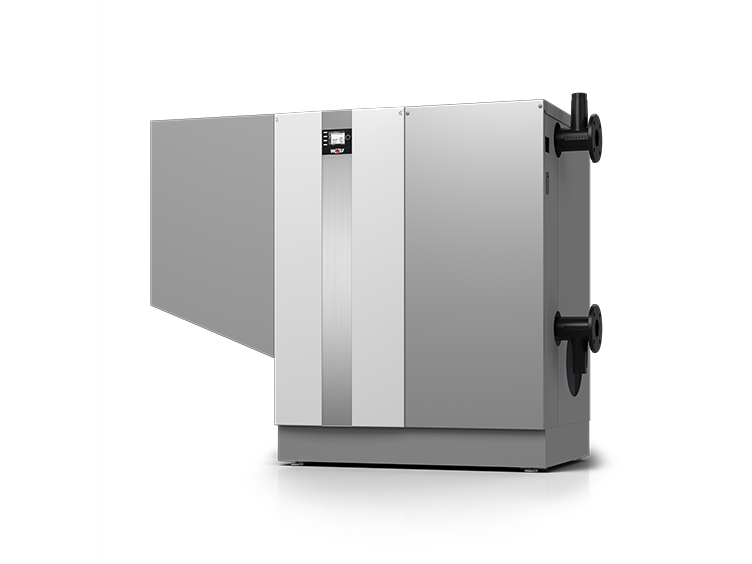
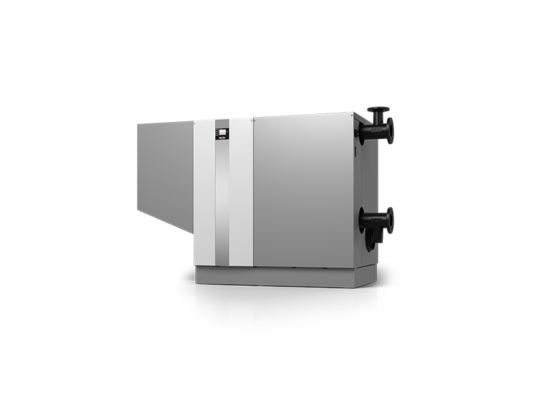
What do you want to know?

Overview of benefits

Very compact dimensions and minimal appliance width for easy handling through 800 mm doorways for MGK-2-390-630 and 1000 mm doorways for MGK-800/1000

Integrated spread control for optimised utilisation of the boiler’s condensing effect and minimal power consumption by the boiler circuit pump

Extremely clean combustion, high standard seasonal efficiency up to 110% (net cv) / 99% (gross cv) for the best possible energy efficiency

Modulating output control from 17 - 100%

Can be combined with BM-2 programming unit or AM display module

Slots for pallet truck or forklift forks for easier handling

Gas condensing boiler can be split. Heat exchanger and gas/air connection can be split for easy handling in tight spaces

Removable covers for direct access during adjustment and maintenance tasks

Heat exchanger made from proven aluminium-silicon alloy with full thermal insulation

Cascades of up to 5 gas condensing boilers can cover output ranges up to 5 MW

Integrated back draught safety device for cascade operation

Does not require return flow heating or a minimum water circulation volume

Quick, easy installation thanks to prefitted casing; fully prepared for direct connection to power and water supply

Neutralising system set with booster and condensate removal pump can be integrated into the casing

Communication with 0-10V input for optional integration into BMS systems via smartphone, laptop or PC using WOLF Link home LAN/WiFi module

Specifications

MGK-2 390-100
Model type
MGK-2
390
470
550
630
800
1000
General data
Rated heating output at 80/60°C
kW
366.7
434.7
511.6
584.4
700
931
Rated heating output at 50/30°C
kW
392
467.1
549.2
626.6
752
1000
Rated heat input
kW
371.2
443.6
521
593.9
710
942
Lowest heating output (modulating) at 80/60°C
kW
58.5
70.7
84.5
96.7
133
174
Lowest heating output (modulating) at 50/30°C
kW
64.2
78.7
94
106.8
119
157
Lowest heat input (modulating)
kW
59.5
73.2
86.8
98.5
122
160
Heat input modulation range
%
17-100
17-100
17-100
17-100
17-100
17-100
Amount of condensate at 40/30°C
l/h
39
46
52
59
77
93
Condensate pH value
approx. 4.0
approx. 4.0
approx. 4.0
approx. 4.0
approx. 4.0
approx. 4.0
Water capacity of the heating water heat exchanger
litres
50
56
62
68
80.5
92.6
Max. permissible boiler pressure
bar
6
6
6
6
6
6
Max. permissible flow temperature
°C
90
90
90
90
90
90
Available gas fan draught
Pa
150
150
150
150
200
250
Standby losses excess temperature 30 / 50 K
%
0.11 / 0.18
0.10 / 0.17
0.09 / 0.15
0.09 / 0.14
0.07 / 0.13
0.06 / 0.10
Flue gas temperature 80/60-50/30 at Qmax
°C
65-35
65-35
65-35
65-35
65-42
65-40
Flue gas temperature 80/60-50/30 at Qmin
°C
60-30
60-30
60-30
60-30
62-32
62-32
Max. flue gas mass flow rate
g/s
156.3
185.2
225.3
247.4
307
407
Flue gas category to DVGW G 635
G 52
G 52
G 52
G 52
G52
G52
Heating water pressure drop with 20 K spread
mbar
120
113
126
118
127
123
IP rating
IP20
IP20
IP20
IP20
IP20
Sound power to DIN EN 15036 Part 1, balanced flue
dB(A)
61
66
68
68
67.7
73.3
Sound pressure level 1 m away from MGK-2, room sealed 2)
dB(A)
44
49
50
50
85.1
83.5
Sound power to DIN EN 15036 Part 1, open flue
dB(A)
78
82
84
84
65-70
70-75
Sound pressure level 1 m away from MGK-2, open flue 2)
dB(A)
60
64
65
65
82-87
80-85
Efficiency
η 80/60 at Qmax
%
98.8
98
98.2
98.4
98.7
98.8
η 50/30 at Qmax
%
105.6
105.3
105.4
105.5
106
106.2
η TR30 at 30%
%
107.8
108.9
108.6
107.6
108.8
110
Standard seasonal efficiency
At 40 / 30°C
%
109.9
110.1
110.3
110.4
110.1
110.1
At 75 / 60°C
%
106.4
106.4
106.3
106.3
106.3
106.3
Total height
A mm
1460
1460
1460
1460
1460
1460
Total width / width excl. gas/air connection
B mm
1860/1295
2265 / 1700
2265 / 1700
Total depth / depth excl. casing
C mm
850 / 790
850 / 790
850 / 790
850 / 790
970 / 950
970 / 950
Flue diameter
mm
250
250
250
250
250
250
Combustion air supply
mm
200
200
200
200
200
200
Heating flow
DN
80 PN6
80 PN6
80 PN6
80 PN6
100/6
100/6
Heating return
DN
80 PN6
80 PN6
80 PN6
80 PN6
100/6
100/6
Gas connection
R
2“
2“
2“
2“
2.5
2.5
Balanced flue
Type
B23, B23P, C33, C43, C53, C63, C83, C93
B23, B23P, C43, C53, C63, C83, C93
Gas connection value:
Natural gas E/H (net cv = 9.5 kWh/m³ = 34.2 MJ/m2)
39.1
46.7
54.8
62.5
75
99.5
Natural gas LL (net cv = 8.6 kWh/m³ = 31.0 MJ/m³)
43.2
51.6
60.6
69.0
80.3
106.6
Gas supply pressure: Natural gas E/H/LL
mbar
20
20
20
20
20
20
Weight
Total weight (empty)
kg
390
420
450
480
Electrics
Electrical connection for fuse protection
V~/Hz
1~ NPE / 230VAC / 50Hz / 10A/B alternatively: 3~ NPE / 400VAC / 50Hz / 10A/B
1~ NPE / 230 V AC / 50 Hz / 10 A/B
3~ NPE 400VAC/50Hz
Output heating circuit pump/ZHP fuse
V~/Hz
1~ NPE / 230VAC / 50Hz / 4A alternatively: 3~ NPE / 400 V AC / 50 Hz / 4 A
1~ NPE / 230 V AC / 50 Hz / max. 7 A
Power consumption (partial load/full load)
W
42 - 410
45 - 490
48 - 580
50 - 660
50 - 850
60 - 1835
Standby power consumption
W
8
8
8
8
8
11

Specifications

MGK-2 390-100
  • 390

  • 470

  • 550

  • 630

  • 800

  • 1000

    General data
    Rated heating output at 80/60°C (kW)
    366.7
    434.7
    511.6
    584.4
    700
    931
    Rated heating output at 50/30°C (kW)
    392
    467.1
    549.2
    626.6
    752
    1000
    Rated heat input (kW)
    371.2
    443.6
    521
    593.9
    710
    942
    Lowest heating output (modulating) at 80/60°C (kW)
    58.5
    70.7
    84.5
    96.7
    133
    174
    Lowest heating output (modulating) at 50/30°C (kW)
    64.2
    78.7
    94
    106.8
    119
    157
    Lowest heat input (modulating) (kW)
    59.5
    73.2
    86.8
    98.5
    122
    160
    Heat input modulation range (%)
    17-100
    17-100
    17-100
    17-100
    17-100
    17-100
    Amount of condensate at 40/30°C (l/h)
    39
    46
    52
    59
    77
    93
    Condensate pH value
    approx. 4.0
    approx. 4.0
    approx. 4.0
    approx. 4.0
    approx. 4.0
    approx. 4.0
    Water capacity of the heating water heat exchanger (litres)
    50
    56
    62
    68
    80.5
    92.6
    Max. permissible boiler pressure (bar)
    6
    6
    6
    6
    6
    6
    Max. permissible flow temperature (°C)
    90
    90
    90
    90
    90
    90
    Available gas fan draught (Pa)
    150
    150
    150
    150
    200
    250
    Standby losses excess temperature 30 / 50 K (%)
    0.11 / 0.18
    0.10 / 0.17
    0.09 / 0.15
    0.09 / 0.14
    0.07 / 0.13
    0.06 / 0.10
    Flue gas temperature 80/60-50/30 at Qmax (°C)
    65-35
    65-35
    65-35
    65-35
    65-42
    65-40
    Flue gas temperature 80/60-50/30 at Qmin (°C)
    60-30
    60-30
    60-30
    60-30
    62-32
    62-32
    Max. flue gas mass flow rate (g/s)
    156.3
    185.2
    225.3
    247.4
    307
    407
    Flue gas category to DVGW G 635
    G 52
    G 52
    G 52
    G 52
    G52
    G52
    Heating water pressure drop with 20 K spread (mbar)
    120
    113
    126
    118
    127
    123
    IP rating
    IP20
    IP20
    IP20
    IP20
    IP20
    Sound power to DIN EN 15036 Part 1, balanced flue (dB(A))
    61
    66
    68
    68
    67.7
    73.3
    Sound pressure level 1 m away from MGK-2, room sealed 2) (dB(A))
    44
    49
    50
    50
    85.1
    83.5
    Sound power to DIN EN 15036 Part 1, open flue (dB(A))
    78
    82
    84
    84
    65-70
    70-75
    Sound pressure level 1 m away from MGK-2, open flue 2) (dB(A))
    60
    64
    65
    65
    82-87
    80-85
    Efficiency
    η 80/60 at Qmax (%)
    98.8
    98
    98.2
    98.4
    98.7
    98.8
    η 50/30 at Qmax (%)
    105.6
    105.3
    105.4
    105.5
    106
    106.2
    η TR30 at 30% (%)
    107.8
    108.9
    108.6
    107.6
    108.8
    110
    Standard seasonal efficiency
    At 40 / 30°C (%)
    109.9
    110.1
    110.3
    110.4
    110.1
    110.1
    At 75 / 60°C (%)
    106.4
    106.4
    106.3
    106.3
    106.3
    106.3
    Total height (A mm)
    1460
    1460
    1460
    1460
    1460
    1460
    Total width / width excl. gas/air connection (B mm)
    1860/1295
    2265 / 1700
    2265 / 1700
    Total depth / depth excl. casing (C mm)
    850 / 790
    850 / 790
    850 / 790
    850 / 790
    970 / 950
    970 / 950
    Flue diameter (mm)
    250
    250
    250
    250
    250
    250
    Combustion air supply (mm)
    200
    200
    200
    200
    200
    200
    Heating flow (DN)
    80 PN6
    80 PN6
    80 PN6
    80 PN6
    100/6
    100/6
    Heating return (DN)
    80 PN6
    80 PN6
    80 PN6
    80 PN6
    100/6
    100/6
    Gas connection (R)
    2“
    2“
    2“
    2“
    2.5
    2.5
    Balanced flue (Type)
    B23, B23P, C33, C43, C53, C63, C83, C93
    B23, B23P, C43, C53, C63, C83, C93
    Gas connection value:
    Natural gas E/H (net cv = 9.5 kWh/m³ = 34.2 MJ/m2)
    39.1
    46.7
    54.8
    62.5
    75
    99.5
    Natural gas LL (net cv = 8.6 kWh/m³ = 31.0 MJ/m³)
    43.2
    51.6
    60.6
    69.0
    80.3
    106.6
    Gas supply pressure: Natural gas E/H/LL (mbar)
    20
    20
    20
    20
    20
    20
    Weight
    Total weight (empty) (kg)
    390
    420
    450
    480
    Electrics
    Electrical connection for fuse protection (V~/Hz)
    1~ NPE / 230VAC / 50Hz / 10A/B alternatively: 3~ NPE / 400VAC / 50Hz / 10A/B
    1~ NPE / 230 V AC / 50 Hz / 10 A/B
    3~ NPE 400VAC/50Hz
    Output heating circuit pump/ZHP fuse (V~/Hz)
    1~ NPE / 230VAC / 50Hz / 4A alternatively: 3~ NPE / 400 V AC / 50 Hz / 4 A
    1~ NPE / 230 V AC / 50 Hz / max. 7 A
    Power consumption (partial load/full load) (W)
    42 - 410
    45 - 490
    48 - 580
    50 - 660
    50 - 850
    60 - 1835
    Standby power consumption (W)
    8
    8
    8
    8
    8
    11